 |
Matthew's Portfolio
|


|
|
Matthew's Portfolio
|
|
The first component neccesary for controlling the ball is the resistive touch panel.
The model used was a ER-TP080-1, 8 inch panel from East Rising Technology (link to datasheet). For the purposes of this project, this was a great option based on its simplicity and relatively low price. To interface with the touch panel, there are three different measurments to be made: x-position, y-position, and "z-position" (is the ball in contact with the touch panel). To determine each reading, an analog to digital converter (ADC) must be configured in a slightly different manner. For the two true positional values, the board acts as a voltage divider, with the contact point of the ball defining the division of voltage from the ADC. For measuring the z-component, it is only neccesary to determine if any current is flowing.
Another important aspect of interfacing wtih the touch panel is correct calibration. Values returned from a 12-bit ADC are from 0-4095, so to convert from ADC count to (x,y) coordinates in millimeters, a calibration method and main program instruct the user to press down on a corner and the center of the board, from which linear relations for x and y position can be determined. Additionally, as there can be errors in readings if the ball is out of range of the readable area, the user must select whether to keep a calibration run, or remove its data from the final average calculations. This real-time error checking adds a neccesary human element to the calibration process. (touchPanelCalibration_main.py, source code here)
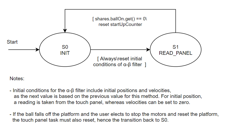
Lastly, the readings recieved from the ADC for the touch panel can be quite noisy, giving rise to the need for filtering. Within the touch panel task (see Figure 8 below for the touch panel task state transition diagram), a few different types of filtering are used. First, positional values must satsify an initial threshold of "acceptable" (based on what the physical limits of readings should be). For a more concrete example, the touch panel used for this project has a readable area of approximately 176 mm by 107 mm, with the origin located at its center. Therefore, a reading of x = 30 mm and y = 40 mm lies within the phyiscal bounds, but a value of x = 90 mm and y = 60 mm is invalid (since both are more than half the board width/length respectively), and should be filtered out.
After this baseline filtering, an alpha-beta filter was used to obtain measurements of both position and velocity with a relatively small amount of computational power needed. Alpha-beta filters are a simplistic version of Kalman filters, and are often used in control applications for data smoothing and estimation. For more information on alpha-beta filters, see the following links:
For documentation of both the driver and task classes related to the touch panel, use the links provided below:
Continue to the next section here: DC Motors: Moving the Platform