 |
Matthew's Portfolio
|


|
|
Matthew's Portfolio
|
|
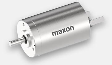
The second hardware componenet to interface with was the DC motors/motor driver.
The combination of motors and motor driver was the actuator of the control system, as the controller's final goal was to determine an appropriate duty cycle for each motor (at a fast rate) to balance the ball. The motor driver used was a DRV8847 Dual H-Bridge Motor Driver from Texas Instruments (link to Interactive Datasheet), and the motors themselves were Maxon DCX 22 S DC Motors (Product Page).
In terms of code implementation, the major difference between motor control employed in ME 305 and ME 405 was the seperation of motor driver from individual motor channels. This divide is desirable because certain methods can be written that affect both motors. For example, the nSleep pin that is used to disable/enable the motor driver applies for both motors. Similarly, the nFault pin can be triggered by either motor, and disables both automatically. The last, more organizational method of the parent motor driver is a method to create motor channel objects from the motor driver chanel class. By giving the parent driver the ability to create motor objects, the driver can store copies of these motors, and disable or enable both at the same time.
In terms of the motor driver channel class, the only method needed is one to configure PWM pins for the correct direction and effort. This method, setLevel(), and the methods of the parent motor driver can be found in the following documentation pages.
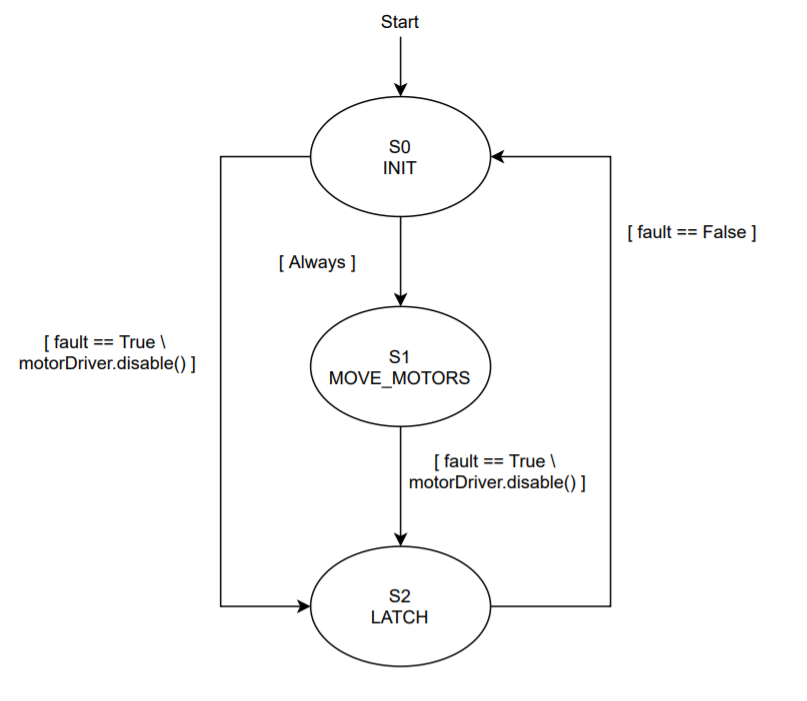
Lastly, the motor task had two main states: moving the motors, and a latch state. In the moving motors state, desired duty cycles are recieved from the controller and are saved to arrays for later analysis. In the case of a fault, the task moves to the latch state, in which a user must manully press the blue user button on the Nucleo board to clear the fault. The state transition diagram for the motor task can be seen below in Figure 10.
For documentation of the motor task, see the below links:
Continue to the next section here: Quadrature Encoders: Measuring Motor Position