 |
Matthew's Portfolio
|


|
|
Matthew's Portfolio
|
|
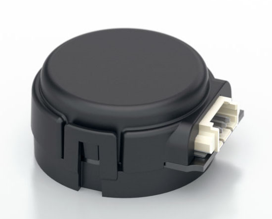
To measure the position of each motor (and subsequently the approximate angles of the board) quadrature encoders were used.
The model selected for this project was an E4T Miniature Optical Encoder (see Figure 11). As with all components for this project, low cost with sufficient performance was the goal (link to E4T Datasheet).
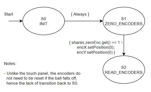
To interface with encoders, there were two main steps to take. First, each needed to be correctly configured. For configuration, a timer object must be instantiated with proper prescaler (how many ticks per count) and period (how many counts to overflow), which for the purposes of this project were 1 and 0xffff (65535) respectively. Secondly, the encoders do not give any warning of overflow/underflow, so we must algorithmically account for this. The algorithm used determined a change in count each time the encoders are updated. If this change in tick count is between -1/2 to +1/2 of the timer period, no correction is needed. However for values outside of this range, the period must be added or subtracted (for underflow and overflow respectively). After neccesary corrections are made, the current delta value is added to the previous position to obtain the current position.
As with all components of this project, a driver class and task were both written for the encoders. The main method of the driver, update(), was responsible for the algorithm discussed above. Additionally, a setPosition() method was utilized for resetting the encoders upon request from the user, such as in the case of zeroing the board before balancing the ball. A method getSpeed() for speed measurement was originally written for the purposes of ME 305, but was not used for this project with the use of filtering in the task. On the task side of things, the alpha-beta filter approach introduced in Resistive Touch Panel: Locating the Ball was again used to estimate position and velocity. These values could then be stored in a shared variable, and accesed by the controller as needed. For the corresponding state transition diagram see Figure 12 below.
For detailed file documentation, see the links below:
Continue to the next section here: User Interface (UI) and Controller