 |
Matthew's Portfolio
|


|
|
Matthew's Portfolio
|
|
With the touch panel, encoders, and motors all setup properly, the user interface and controller were the last two main pieces of the full system.
Before discussing the controller, a brief explanation on how the user interface works is neccesary. Using the USB_VCP module from the micropython library, key presses can be read and used as a direct link between the user and the Nucleo microcontroller (VCP stands for virtual comm port). The key methods used were USB_VCP.any(), which determines if a key has been pressed and data is ready for reading, and USB_VCP.read(), which reads byte data from the virtual comm port object. The UI task does not utilize a finite state machine, but instead checks each run if there is data to be read. If data is available, it is read as an ASCII character code. Finally, if the character read matches one of the available commands, it is sent to the controller to be processed. With this checking system, the controller only needs to handle correct commands from the user. The three available commands are:
Each command can only be used in certain controller states, but these are the three main controls (along with the blue user button for clearing faults) for running the system from a human perspective. However most of the system control is run autonomously, as discussed in the next section.
For documentation of the UI task, see the following links below:
The controller acted as the main hub for information. Feedback in the form of encoder and touch panel readings (position and velocity measurement), as well as commands from the user interface are read by the controller, and from this stream of signals the controller must determine what action to take. For full discussion of the modeling of the controller, see Full-State Feedback. In short, state space control with full-state feedback allows the controller to use multiple signals to determine the needed duty cycle for the motors.
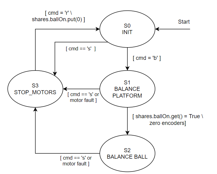
As seen in Figure 13 above, the finite state machine of the controller has four main states. Initially, the controller must wait for the user to press either "b", telling the controller that the platorm is level and the ball can now be placed on the platform, or the user can press "s" to stop the motors. Originally, the plan was to use an Inertial Measurement Unit (IMU) to automate the balancing of the platform, however time constraints limited us to manually leveling the platform. Once the controller recieves a signal from the touch panel task that the ball is on the platform, a transition occurs to the most important state, S2_BALANCE_BALL. In state 2, the controller reads from both encoders and the touch panel for feedback, sends updated duty cycles to the motors, and adds the current feedback data to queues for data collection purposes. From state 2, either a fault can occur or the user can choose to press "s", which both switch the controller to S3_STOP_MOTORS. From state 3, the board can then be reset to try balancing the ball again.
For documentation of the controller task, use the links provided below:
Continue to the next section here: System Integration: Task Scheduling, Data Sharing, and Data Collection