 |
Matthew's Portfolio
|


|
|
Matthew's Portfolio
|
|
Code documentation:
In ME 305, timers and interupt service routines were used frequently. For Part A of this lab, our task was to use the utime module (specifically the methods of utime.ticks_us and utime.ticks_diff) to calculate a user reaction time to an LED flashing. To ensure the user could not predict when the LED would flash, the LED was setup to flash on for 1 second at a time, with a random wait time between 2 and 3 seconds between turning on. This randomization was achieved using the random.randrange() method of the random module. Addtionaly, a simple state machine was utilized, and the corresponding state transition diagram can be found below in Figure 2.1.
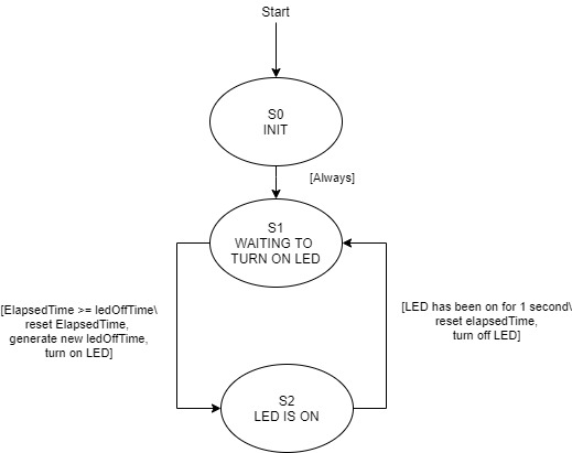
For the interupt callback, the blue user button was setup as an external interupt, which when called could set a boolean variable to True (signifying to the main script) that the button had been pressed and a reaction time should be calculated. Although this code gives a reasonably accurate picture of reaction time, for more advanced physical systems such as those we will work with later in the quarter, timing is essential. A controller cannot effectively do its job if the latency of the system is too high, so we need to figure out a more precise/fast way to track the timing of events.
In Part B of this lab, we moved from the naive way of doing things with code only to more effectively using hardware components accesible on the Nucleo Developement Board. Specifically, two imporant concepts were put into practice:
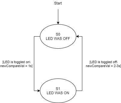
Output Compare: With output compare, a timer channel is set to toggle a specific pin (the LED in our case) whenever a specified output compare value is reached on the count. In terms of code implementation, this requires the timer channel mode to be set to mode = pyb.timer.OC_TOGGLE, as well as a callback to be associated with the compare value being reached. For the ouptut capture callback, a brief state machine was used to differentiate between setting the LED to toggle on after a random time between 2 and 3 seconds, versus setting the LED to turn off after 1 second. In each case, the required interval for the next compare value is added to the previous OC value. See Figure 2.2 below for the associated state transition diagram for the OC interupt.
polarity = timer.FALLING) to trigger an Input Capture callback.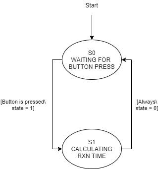
For both parts of Lab0x02, demo videos were created to show program operation.
1. Which method is better for this type of application?
For tracking timing of events occuring relatively quickly, such as reaction time or controlling a precision physical system (such as the Balancing Platform Term Project), the method used in Part B is superior. By using hardware based methods, transitions from one part of code to another are eliminated from the calculation of timing. For example, with the method of Part A, the time for the program to go from turning on the LED, as well as the time between recognizing an interupt has been triggered and actually capturing this time are including in the overall reaction time. This makes for an inaccurate measurement in the case of this lab, and a potentially faulty system in a broader context.
2. Which method would be prefered for a different time scale?
Although the method of Part B is ideally suited for short periods of time between events, it has its downfalls. If the time between events (such as a button being pressed) is greater than the timer period, it becomes much more difficult to process the count value. Keeping track of such overflow would require using a counter for the number of times an overflow occured, and at this point it is likely that the resolution available with hardware would be unnecesary. For these reasons, it is always important to consider the time scale when choosing between hardware or software timing methods.
Click here for the next lab, 405 Lab 0x03: Pushing the Right Buttons.