 |
Matthew's Portfolio
|


|
|
Matthew's Portfolio
|
|
Use code based timing methods to calculate reaction times. More...
Functions | |
| def | Lab0x02_A.onButtonPressFCN (IRQ_src) |
| Callback function for the button press. More... | |
Variables | |
| Lab0x02_A.pinC13 = pyb.Pin (pyb.Pin.cpu.C13) | |
| Pin attribute for blue user button. More... | |
| Lab0x02_A.pinA5 = pyb.Pin (pyb.Pin.board.PA5, mode = pyb.Pin.OUT_PP) | |
| Pin attribute for LED. More... | |
| Lab0x02_A.ButtonInt = pyb.ExtInt(pinC13, mode=pyb.ExtInt.IRQ_FALLING, pull=pyb.Pin.PULL_NONE, callback=onButtonPressFCN) | |
| Callback interrupt attribute. More... | |
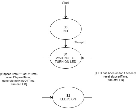
| int | Lab0x02_A.S0_INIT = 0 |
| Initial state. | |
| int | Lab0x02_A.S1_WAITING = 1 |
| State for pause between LED blinking. | |
| int | Lab0x02_A.S2_LED_ON = 2 |
| State for LED on-time. | |
| bool | Lab0x02_A.buttonPress = False |
| Variable to keep track if the button is pressed or not. | |
| Lab0x02_A.zeroTime = utime.ticks_us() | |
| time to compare to in calculating elapsed time since a certain action | |
| Lab0x02_A.ledTime = random.randrange(2000000,3000000) | |
| Off time between LED flashes. | |
| int | Lab0x02_A.ledPeriod = 1000000 |
| Time interval for LED to stay on. | |
| int | Lab0x02_A.state = 0 |
| State machine state variable for mini FSM. | |
| list | Lab0x02_A.rxnTimes = [] |
| List to hold the reaction times (later will be averaged) | |
| int | Lab0x02_A.avgRxnTime = 0 |
| Variable to display the average of the reaction times. | |
| Lab0x02_A.currentTime = utime.ticks_us() | |
| current time in microseconds | |
| Lab0x02_A.elapsedTime = utime.ticks_diff(currentTime, zeroTime) | |
| elapsed time since zeroTime was last reset (microseconds) | |
| bool | Lab0x02_A.calculate = True |
| Should the program calculate a reaction time? | |
| Lab0x02_A.thisRxnTime = elapsedTime | |
| current reaction time (microseconds) | |
Use code based timing methods to calculate reaction times.
Using the Nucleo L476RG board and code/software based methods, the reaction time of a user pressing the B1 button will be measured when the LD2 LED turns on. For Part A of this lab, the LED is turned on and off using the high() and low() methods for a pin. The LED will be on for 1 second each time (controlled through a state machine), and will turn off for a random time between 2 to 3 seconds. Once the user sees the LED flash on, they will press the button, triggering a callback and starting the sequence of calculating a reaction time. Although this method works, it is not the most effective or accurate. Part B of the lab covers a hardware based solution that improves upon Part A.
See source code here: https://bitbucket.org/ryanmclaug/matt_ryan_shared/src/master/405_Lab0x02/Lab0x02_A.py
| def Lab0x02_A.onButtonPressFCN | ( | IRQ_src | ) |
Callback function for the button press.
When the button is pressed, the onButtonPressFCN function will be called. In the constructor, buttonPress is set to False, such that when it is pressed, it switches to True. Likewise, since the button is set to detect both rising and falling edges, the button returns to False when released. Based on use of the not operator.
| Lab0x02_A.ButtonInt = pyb.ExtInt(pinC13, mode=pyb.ExtInt.IRQ_FALLING, pull=pyb.Pin.PULL_NONE, callback=onButtonPressFCN) |
Callback interrupt attribute.
When a rising or falling edge is detected by the button, the interupt will be triggered.
| Lab0x02_A.pinA5 = pyb.Pin (pyb.Pin.board.PA5, mode = pyb.Pin.OUT_PP) |
Pin attribute for LED.
Similar to pinC13, but for the output LED.
| Lab0x02_A.pinC13 = pyb.Pin (pyb.Pin.cpu.C13) |
Pin attribute for blue user button.
The blue button on the board serves as the main user input interface, and therefore needs a pin assignment.