 |
Matthew's Portfolio
|


|
|
Matthew's Portfolio
|
|
In the third week of the final project, the motors actually got to spin.
Since this was the most basic form of spinning the motors, A P controller was implemented to match a step input to the motor (essentially, set the motor to a specific speed) using a P controller. This required starting a few more classes and program structure than the previous weeks. First, the encoder task (created in Week 2) turned into a controller task (as seen here: ctrlTask.py). This interfaced with a motor, encoder, and controller driver, which, combined, created a working motor controller system to react to the step input. All of the files (albiet it, in their final form) are listed here.
–controllerdriver.controllerdriver
The workflow was that the main.py file created instances of the uiTask.py and ctrlTask.py classes. Within the ctrlTask.py file, instances of the encoders motors, and controller drivers were created. Since more commands were now being shared, shares.py was implemented in order to have a space for values and commands that would trigger actions in the controller task.
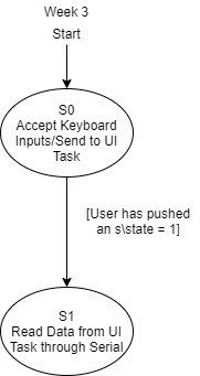
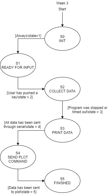
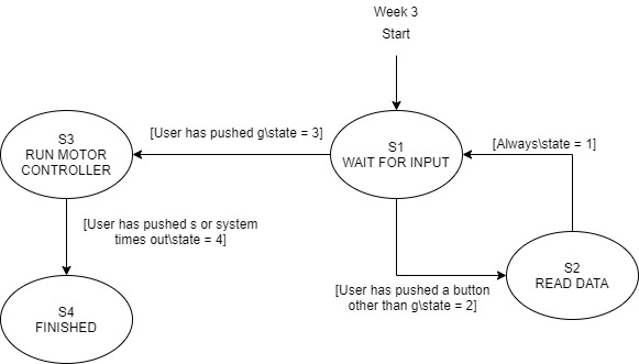
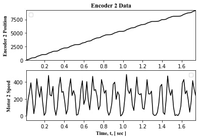
There were several state and task diagrams created, which can be viewed within the specific files themselves. The files containing state diagrams include the ctrlTask.py, uiTask.py, and PC_FrontEnd.py. There also was a task diagram within shares.py that helps show the utility of the script. Another major portion of the lab was dedicated to tuning the proportionality constant, Kp, in order to try and get the system to match the speed faster and with less oscillation. Below are a few plots that show the response of the system, and the figure captions highlight the different Kp values that were tested. The last figure shows the best option found, and although it still has some oscillation, this was due to a few factors that Week4 will hopefully fix. First, without a Ki (or Kd if we were doing a PID controller), it's hard to get a perfect system, because if the system overshoots, it will set the motor to backwards, and reverse the direction. This is a large part that accounts for the oscillation. Having a Ki will help keep the system in the positive/negative region (whichever is applicable at the time) and can adjust the speed without fully changing the motor to reverse – essentially it helps maintain a bit of the buffer so that the system has less oscillation. Another reason that aludes to the oscillation is the frequency at which the controller driver is being called. If it's called faster, it will have more of a chance to adjust and correct the behavior of the motor with a finer resolution. However, due to memory constraints on the Nucleo, it was hard to get a much finer resolution than is seen in the figures.

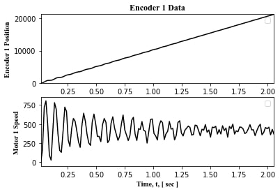
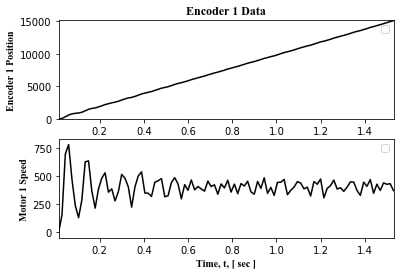
As can be seen in the plots, lowering Kp helped the motor zero onto the desired speed. However, as can be seen in the following figure, lowering Kp too drastically had negative results.
Below is a summary of the state diagrams utilized for the week. These stayed fairly consistent between weeks (the overall flow stayed the same, we were just exporting/sending more data with each week).