 |
Matthew's Portfolio
|


|
|
Matthew's Portfolio
|
|
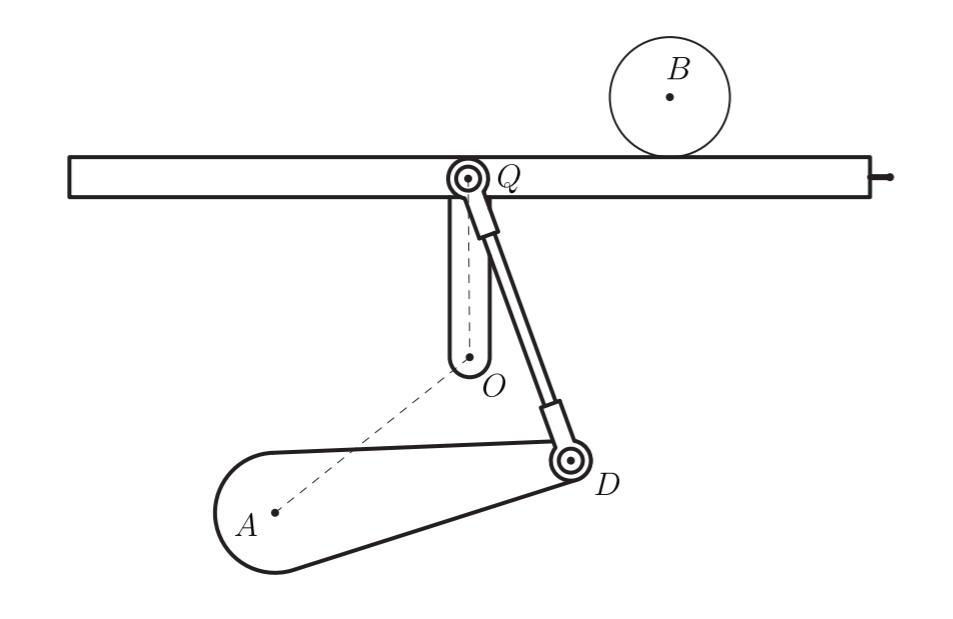
In the first homework assignment for this project included modeling the dynamics and kinematics of the ball and platform. Figure 2 shows the schematic of the platform as provided by the HW0x02 handout.
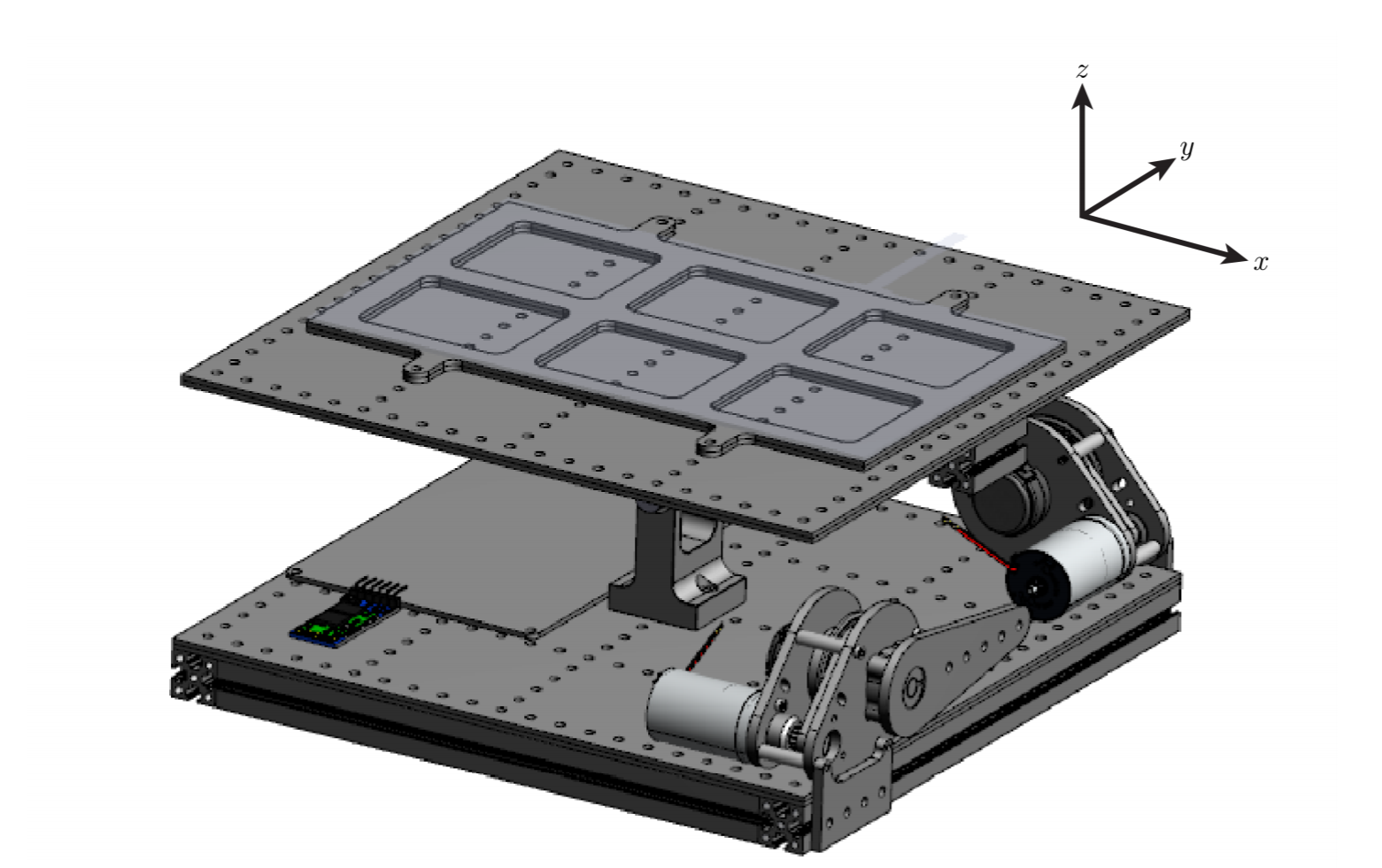
Additionally, visualizing the connection between the motor and platform is critical to fully understand the test setup. Figure 3 shows the connection between the motor and platform. It consists of a motor arm AD and push-rod DQ.
After defining the geometry and such of the model, the kinematics of the ball were analyzed. This was done by defining the location of the ball in the global frame of reference, and then differentiating the equations to find the velocity and acceleration of the ball. Along with finding the kinematics of the ball, a relationship between the motor speed and platform angular speed was derived.
To accomplish these, several simplifying assumptions were utilized, which will be summarized below:
After deriving the kinematics, the kinetics were analyzed. First, the force from the motor was translated into a resultant force and moment on the platform. This was done with a method named 'virtual work,' where the input of work from the motor is imposed on the platform with no loss of energy. This will simplify the kinetics in the future.
To accomplish these, the main simplifying assumption is listed as such:
Now that the model has been simplified down, two separate FBDs and MADs were created. The first system included the platform and ball as one. This produced a set of equations when moments were summed about the pivot point. The second system was solely the ball, with moments being summed at the contact point. This eliminates the unnecessary friction and normal force from the equations and generates another eqaution of motion. Once these are derived, they are put into matrix form in terms of the linear acceleration of the ball relative the platform and the angular acceleration of the platform. These will be used in future assignments to allow for control of the system.
Continue to the next section here: Linearization EOMs and Simulating Closed-Loop Control