 |
Matthew's Portfolio
|


|
|
Matthew's Portfolio
|
|
Once all the files were written, 20-25 hours of tuning was required in order to successfully balance the ball on the platform.
This page will discuss the major aspects of the program that needed to be tuned, as well as any issues that were encountered in the system.
The majority of tuning revolved around modifying the system gains of the full-state feedback controller. These gains were defined in the main script from which all task objects were instantiated. For detailed documentation of the main script, see main.py (Main Script Source Code). While these were derived in HW0x05, that model was based on a very idealized system, so it was bound to not work perfectly. This tuning took the most time, as there were 8 values that could be modified, and had to be tested after each modification.
When tuning the K matrix, several aspects were kept in consideration. First, the ball has to have a medium-large gain for the position, as this is what is telling the ball to move toward center if it's on the edge but with little velocity or tilt. However, with too significant of a position gain, the platform exhibits a large amount of overshoot. To combat this, the velocity gain was increased. The reasoning behind this is you want the platform to respond to the increasing velocity in order to slow the ball. This essentially increases the daming in the system and aims to prevent as much overshoot.
While increasing velocity helps prevent overshoot, the next issue is that the platform will be tilted too much, so the ball will be quickly changing between large positive/negative velocities. Thus, the platform tilt gain must be large in order to try and keep the platform level. This helps reduce the possibility of a very large velocity, too.
As expected, having a faster controller helps improve the reaction time of the system, however, too fast of a controller does the opposite. If tasks are being run faster than they can be completed, or, if they're run before the necessary data is recorded, the system slows, and performs worse. Tuning was required in order to find the faster frequencies while not running tasks late.
Another portion of testing required modifying the platform setup in order to create the best performing system. First, the motor locations and push-rod lengths were adjusted so that the pushrods were vertical while the motor arms were horizontal. This was a simplifying assumption made within the calculations of HW0x02, so it felt fitting to do the same on the board.
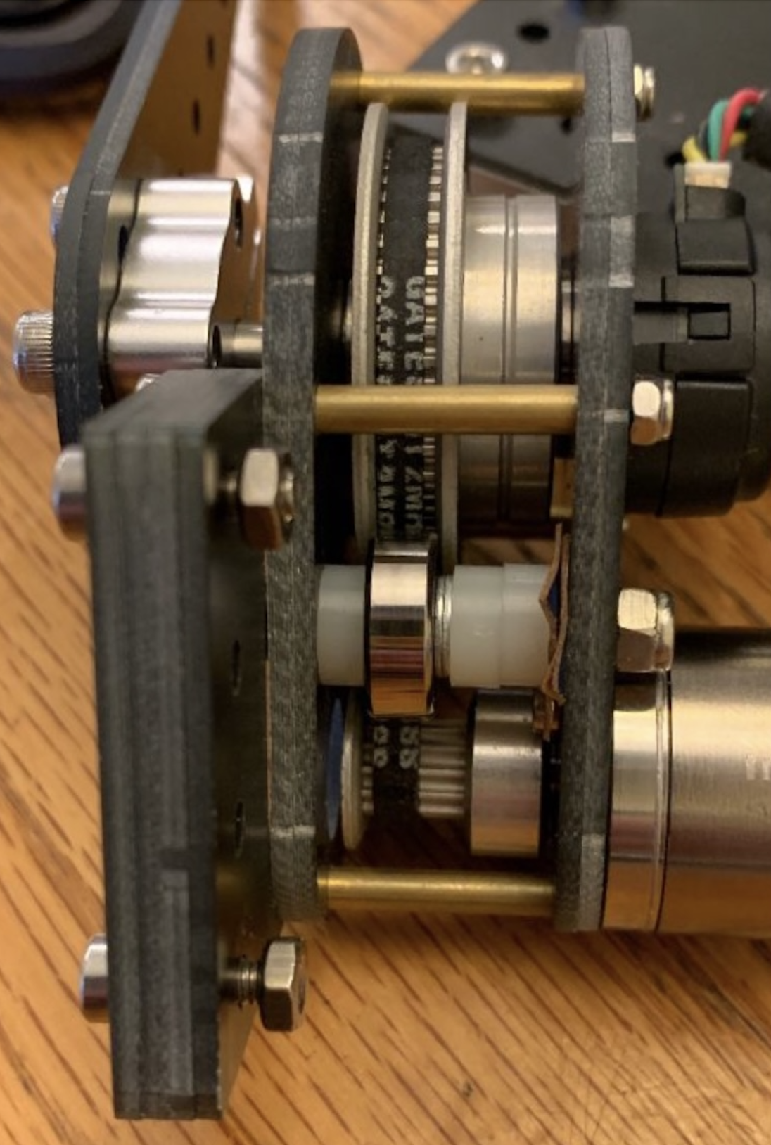
A belt tensioner was not provided in the lab kit, however, it would have been quite useful. When testing, it could be seen and heard that the belt was slipping if there was too sudden of a movement, so the team when to the hardware store and created their own, as seen in Figure 15. This fixed the issue with the belt slipping, however, it added too much stiction to the motors, which reduced their ability for finer movements. Unfortunately, the tensioner was removed, but could be reintegrated if the belt had one more tooth.
Another modification was the ball. Provided was a rubber-coated steel ball, however, the rubber seam created a non-spherical surface. Through testing, it was found that the ball would get stuck on the platform simply because it was not round. It also wasquite light, so it would hop off of the platform easier. For these reasons, a steel ball bearing was used, which was much heavier, but spherical. This had much better results, but required new tuning values.
The last modification included attaching the motor arms to the looser side of the eccentric pulley. This was done so that less stiction was in the system.
Continue to the next section here: Final Results: Evaluation of System Performance